Solution
Our solution was to modify
the existing design to make it more accurate. To do this, we used the
following circuit for each individual level.
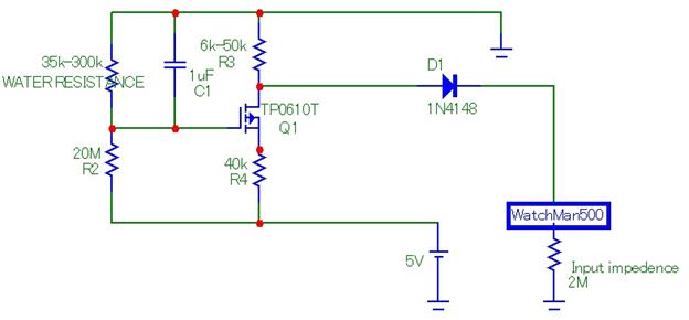
When
the water level goes up and reaches two contacts the transistor is
turned on and conducts current from drain to source across a pair of
resistors (R3 and R4). This MOSFET design eliminates the inaccuracies
due to different water conductivities, and instead gives us distinct
levels based on the resistor R3. The lowest level has the smallest R3,
and with each subsequent level having an increased R3 based on the
desired increment level, determined by the difference between R3 and
R4.
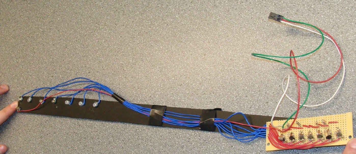
Below
is a picture of our prototype using n-channel MOSFETS, and a video
showing it in use:
http://www.youtube.com/watch?v=JCtOH4qqDNE
After showing this prototype to Axys, we discovered a problem we had
not anticipated. The current between the positive sensor contact and
the buoy wall was large enough to produce hydrogen from electrolysis.
The solution was to switch to the p-channel MOSFET circuit shown at
the top of the page. This limited the current in the water to just
nanoamps.
Full design report can be found here.
Interim report can be found
here.