ECOSat Communications Subsystem: RF Division
The RF communications team designed the receiver and transmitter for the communications system.
Team Biography
Jarrah Bergeron
Jarrah is currently a fourth year electrical engineering student. Originally from northern British Columbia, he moved to Victoria for post-secondary education. He is currently taking courses in the communications, digital signal processing and microwave and optics and will likely specialize in microwaves and photonics. Also, past co-op work include various board-level verification and debugging, digital logic and analog design and validation, extensive documentation and photonics research. Jarrah has experience in many schematic capture and PCB layout packages, circuit simulators and software and firmware development environments. However, his experience in electrical and electronics spans far before university, having broad knowledge in a variety of domains and done numerous projects namely in embedded development. This includes microcontrollers, digital logic and analog audio design both in theory and on PCB. Many types of test equipment have also been used including power supplies, power analysers, oscilloscopes and spectrum analysers. Interests mainly lie in high frequency analog and digital hardware and system design.
For this project, he has been part of and has contributed to the ECOsat project for many months and knows how the satellite team is organized and how the project is progressing, including most subsystems. Along with the breath on knowledge already acquired prior involvement in ECOSat makes Jarrah particularly well suited for this project. This will allow our project to start with little delay and help meet the project deadlines.
Kris Dolberg
Kris is a fourth year electrical engineering student planning to specialize in digital signal processing and mechatronics. Kris was born in Ottawa, and grew up in Victoria. After finishing high school in 2006, Kris attended Camosun College where he took two years of general studies. He enrolled in the University of Victoria's engineering program in 2008. Originally planning study mechanical engineering, he chose to study electrical after completing first year do its better fit for his interests.
Kris has previously completed two co-op work terms. The first was in the IT department of Odlum Brown Limited, a Vancouver-based investment firm. The second was working for UVic's own VENUS project. He has been involved with ECOSat since 2011. Aside from the work for ELEC 399, Kris is currently designing the drive circuitry and redesigning the coils for the satellites magnetic torquers. Upon graduating, he plans to move to Germany and pursue a career in control system design. In his spare time, he enjoys playing guitar, philosophizing, swing dancing, biking, cooking, and indoor rock climbing.
Project Layout
Purpose of the Communications System
Below, the numerous purposes and tasks of the communications system are outlined.
- Telemetry: The communications system will be used to transmit data produced by the experiments in the diamagnetic payload back to Earth.
- Amateur radio repeater: The ECOSat communications system will be used to relay signals sent by amateur radio broadcasters.
- Communications research: The ECOSat communications system will be capable of implimenting multiple software defined radio modulation schemes for experimental purposes.
- Updates: The communications system will also be used to deliver firmware updates to the satellite when necessary.
Transmitter
The transmitter receieves a 10.7 MHz analogue signal. This signal has been modulated using a software-defined radio and converted to analogue. On the transmitter board, the signal is bandpass filtered to remove noise. It is upconverted by being mixed by a 446.4 MHz local oscillator and filtered again. The signal is amplified twice and and then goes to the antenna where it is transmitted at 435.7 MHz and a power of 1 to 2.5 W.
![]()
The Altium 3D representation of the transmitter board is shown below with labels for each component. 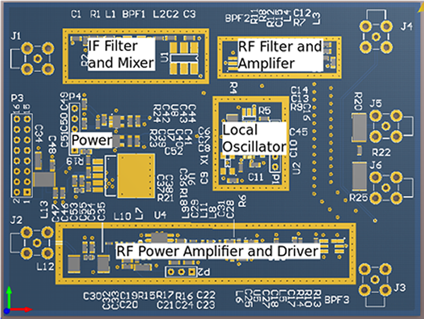
Receiver
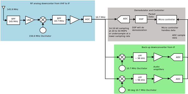
The receiver board first bandpasses the output of the antenna so that only the received frequency of 145 MHz gets through. The filtered signal is amplified by a low noise amplifier. The output of the amplifier is mixed with a local oscillator of 156.6 MHz. The mixed signal is again bandpass filtered to 10.7 MHz. The result is an upconverteed signal at 10.7 MHZ. The output of the bandpass filter is amplified and then passed through an amplifier with automatic gain control. The result is a signal with a constant signal level. The signal is finally received by the modem where it is converted to digital and demodulated by a digital signal processor.
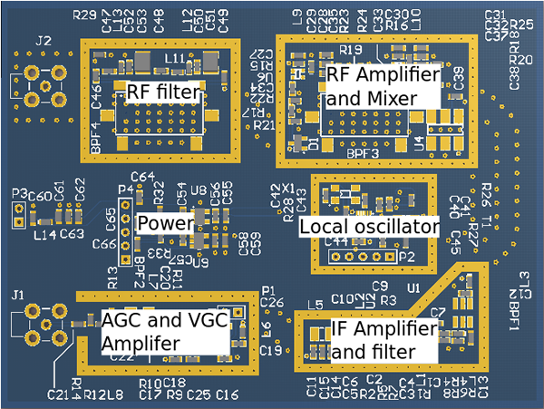
 The Altium 3D representation of the receiver board is shown below with labels for each component.
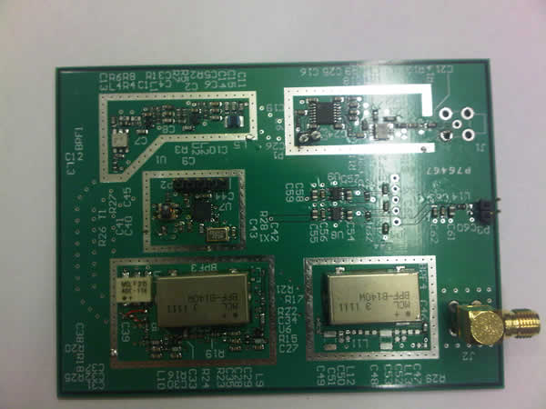
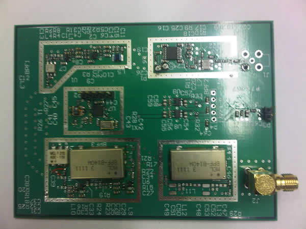
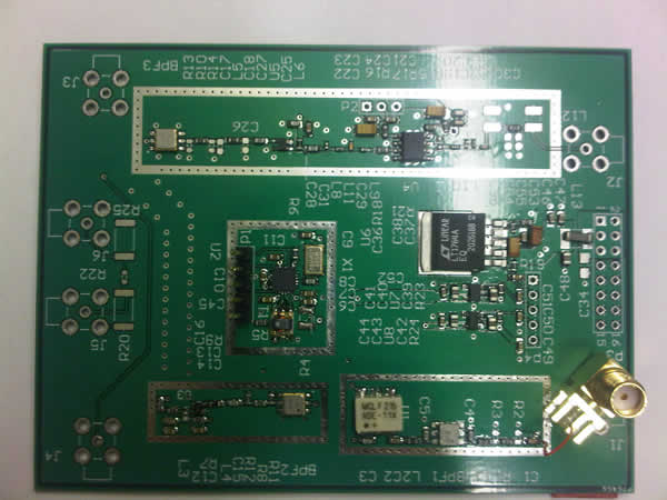
More Pictures
Below, are two photographs of the receiver board
Reports and Other Documents